Selecting the Optimal Strainsert Load Pin
Finding the best Strainsert Load Pin for your specific application is critically important. The correct Load Pin Design will result in an accurate, unique, and cost effective Force Measurement Solution. Pursuing the wrong, or non-optimized solution, can lead to delays, extra costs and frustration.
For over five decades, Strainsert has pioneered the force sensor industry. Our innovative Load Pin designs are made possible by our patented internal gaging process and an unsurpassed dedication to engineering and customer requirements.

Standard Load Pins:
Strainsert offers a comprehensive selection of standard and customizable load pins, ranging from our CPA/CBA Series to a fully customized design solution. See the illustration below for the main Series of load pins available and their applications. Many common standard Load Pin sizes are stocked as part of our Quick Ship Program for expedient delivery.
Custom Load Pins:
The majority of Load Pins that we design and manufacture are custom Load Pins. The pins are designed specifically for the exact application geometry and measurement requirements/specifications. The result is typically a “drop-in” Pin sensor requiring minimal modification by the user to incorporate the Load Pin into the assembly, which often times saves time and money.
Custom Applications Strainsert has Designed Load Pins for include:
• Aircraft Components
• Actuator Clevis Ends
• Automotive System Tests
• Marine Towing Monitors
• Crane and Hoist Controls
• Sheaves with Variable Angles
• Joints with Rotating Members
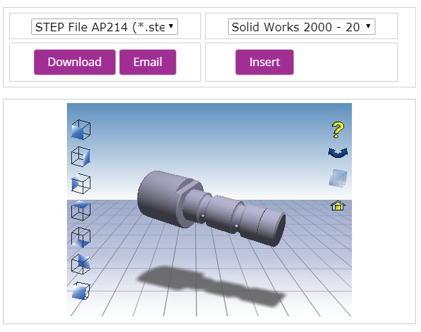
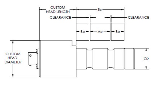
In order to capture and define application requirements, Strainsert has developed a proven approach for custom designs which includes detailed questionnaires as well as a “Custom Load Pin Configurator” to help define the physical layout of the pin. After capturing all requirements, a certified Drawing is provided to the customer for review and sign-off prior to manufacturing to ensure all requirements were incorporated correctly.
Load Pin Questionnaire
Sheave Pin Questionnaire
Load Pin Configurator
The first step in defining the pin requirements is to determine how the forces are applied and the required measurement capacity of the pin.
1. What is your load capacity? (lbs, kips, Kn, etc.) This is how much you want to measure otherwise called your working load.
2. What is my Factor of Safety? This is how much protection from overload that you want the load pin to have. This can be based on the Material Ultimate Strength or the Material Yield Strength (e.g. 3 to 1 based on material Ultimate Tensile Strength (UTS)).
3. How is the Pin Loaded?
• Fatigue or Multiple Cycles
• One way (0 to Full Scale) or fully reversed (± Full Scale)
• Impact load (rapid application of force)
• Static (Loads are applied slowly or are constant)
4. Loading Configuration?
• Single Axis (one load direction)
• One way (0 to Full Scale) tension or fully reversed (± Full Scale)
• Dual bridge (two independent bridge circuits) Typically, one bridge is used as a backup or feedback control
• Bi-Axial (two load directions or axes at 90 degrees). Resultant and load direction can be determined from this configuration.
5. Clevis Configuration and Layout
• Define the clevis dimensions

The next step would be to define any specific design features that would assist ease of installation and in-service operation.
• Radial or Side mounted connector
• Permanently attached Cable
• Anti-rotation plates and brackets (keeps the pin aligned with the load direction and prevents removal)
• Threaded Retention or Retaining Ring Retention
6. Electrical/Instrumentation Requirements
If you’re planning on using your Data Acquisition System or Instrumentation Equipment, be sure to specify the type of pin output that is required for proper interface.
• Typically: mv/V
• Optional: 4-20 ma (amplified)
• Optional: 0-10 Volt (amplified)
If you would like help in selecting an instrumentation package, please contact our Instrumentation Department at 610-825-3310 x115 for assistance or use our online contact form.
7. Environmental Requirements
To correctly select the appropriate materials and to test the pin over the intended application requirements, it is important to specify the service environment that the pin will experience. Examples shown below.
• Indoor / Outdoor Environment
• Hot or Cold Service Temperature Range
• Submerged Environment
• Out-Gassing Requirement.
8. Special Requirements
With a custom designed Load Pin, we can incorporate many special features into the Load Pin design. The features can again facilitate installation and retention attributes as well as other special testing requirements.
• Lubrication Ports
• Variety of Pin Materials and Coatings
• Passivation
• Special Marking Requirements
• First Article Testing
• Non-Destructive Testing Requirements
o Liquid Penetration Testing
o Magnetic Particle Testing
o Ultrasonic Testing
Please contact us to discuss your standard or custom Load Pin applications.
